Heat-set inserts in 3D printed parts: geometry, temperature, and repeatable assembly
الملحقات الملولبة الحرارية في القطع المطبوعة: الهندسة والحرارة والتجميع
By Let’s 3D Studio · 3 min read
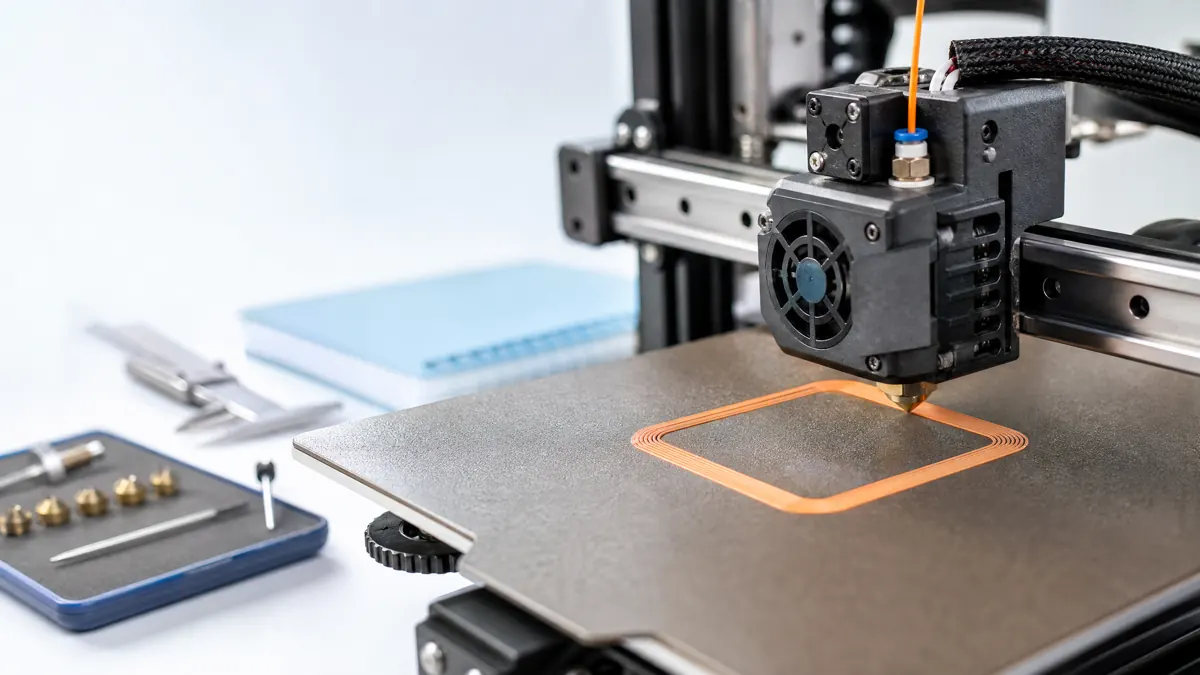
Heat-set threaded inserts give a printed plastic part a durable metal thread for repeated assembly. They are useful in enclosures, fixtures, jigs, and products that must be opened more than once. Good results come from the combination of an insert suited to the screw, a boss designed for the printed material, and controlled insertion—not from pressing an arbitrary brass part into a random hole.
Design the boss around a tested insert
Insert suppliers publish dimensions for the insert body, pilot hole, and recommended material families. Use those dimensions as a starting point, then print a small test block because printed-hole behavior varies by nozzle, material, orientation, and flow. A pilot hole that is too large allows the insert to spin or pull out. One that is too small may crack the boss or displace too much molten plastic.
Give the boss enough surrounding wall thickness and use a fillet where it meets the base. Avoid placing an insert too close to a free edge. If the screw will see bending or high pull-out load, reinforce the area with ribs or redesign the load path; an insert improves the thread but does not make a thin plastic wall structural.
Use a controlled insertion tool
An insert tip on a temperature-controlled soldering iron is more repeatable than holding an insert with pliers. Use an appropriate stand, work on a stable nonflammable surface, protect hands and eyes, and keep the hot tool away from cables and flammable materials. Set a moderate tool temperature that lets the insert sink with gentle pressure; follow the insert and filament guidance rather than using maximum heat.
Press straight down. Do not twist the insert aggressively because rotation can tear the softened hole. Stop with the insert flush or at the depth specified by the design, then allow the plastic to cool without loading it. A simple printed alignment jig can keep the iron perpendicular for a run of identical parts.
| Design check | Why it matters |
|---|---|
| Correct insert and screw thread | Prevents damaged threads and misleading fit tests |
| Tested pilot hole | Accounts for your printer’s actual hole behavior |
| Reinforced boss | Limits cracking and pull-out under assembly load |
| Perpendicular insertion | Keeps the screw aligned and reduces side stress |
Validate the assembly
After cooling, thread in the intended screw by hand. It should engage smoothly without cross-threading. Test the enclosure or fixture through several assembly cycles, then inspect the boss for whitening, cracks, rotation, or deformation. If the insert spins, revise the pilot hole or boss geometry rather than adding adhesive as a first response.
Heat-set inserts create a repeatable interface between a printed form and ordinary hardware. With a documented test block, a safe insertion setup, and geometry that respects the load, they make printed assemblies easier to service and far more durable.