How to fix warping: build surface, heat, geometry, and cooling decisions
By Let’s 3D Studio · 19 min read
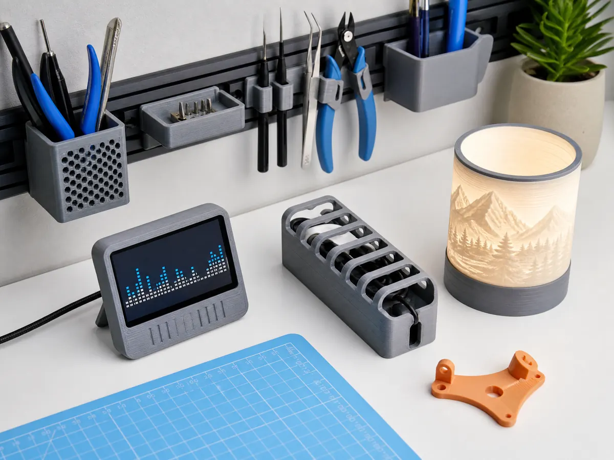
Warping is the quiet saboteur of FDM printing. A part starts flat, then a corner curls or the base peels up, and the rest of the print inherits that internal stress. Fixing warping is not a single switch; it’s a sequence of choices about surface, heat, geometry, and cooling that you tune for the material and the job. This guide lays out practical ranges and decision points you can apply immediately, plus a framework to diagnose the root cause instead of guessing.
What warping is (and is not)
Warping is the out-of-plane deformation caused by nonuniform cooling and shrinkage. When the plastic at the base cools unevenly or faster than upper layers, residual stress bends the part upward, often starting at sharp corners and long straight edges.
Common symptoms and how they differ:
- Warping: Corners lift from the build plate; base edge curves upward; sometimes audible pops as adhesion fails during the print.
- Elephant foot: The very bottom perimeters bulge outward because the bed or first-layer flow is too hot/squished; the base is still flat on the bed. Elephant foot can coexist with warping but is a different fault.
- First-layer under-adhesion: Streaky or incomplete extrusion that never properly sticks. The part may drag immediately. Not warping, but it will lead to detachment and failure.
- Layer splitting (delamination): Visible cracks between layers higher up the part. Often triggered by drafts or low nozzle temperature; warping at the base and delamination up the walls share a root cause: steep thermal gradients.
Understanding which of these you have informs the right fixes.
The physics in one paragraph
Hot plastic expands; as it cools it contracts. If the bottom of the part is colder or constrained differently than the top, the contraction forces don’t cancel and the part bends up. The effect is amplified by:
- Higher material shrinkage during cooling (ABS, ASA, PC, some Nylons).
- Larger flat contact patches and sharp corners that concentrate stress.
- Strong part cooling on early layers or room drafts.
- Large differences between bed, ambient, and nozzle temperatures.
Your countermeasures reduce gradients, improve adhesion margins, and relax geometry where possible.
A quick triage sequence
Before changing everything at once, use this order of operations:
- Surface and first layer: Clean build plate, correct Z offset, adequate first-layer line width and flow, sensible speed.
- Heat: Verify bed temperature, consider a small enclosure or draft shield, avoid cold drafts.
- Cooling: Reduce or delay part cooling fan for warp-prone materials; ensure fan duct isn’t blasting the bed.
- Geometry and anchoring: Add a brim or mouse ears; round corners; break long edges; orient the part to reduce free length on the bed.
- Material-specific tactics: Use a surface or adhesive appropriate to the filament; dry hygroscopic materials.
- Environmental control: Enclosures for ABS/ASA/PC/Nylon when practical; keep electronics and PTFE limitations in mind.
Build surface choices: what sticks, when, and why
Not every plate is equal, and matching surface chemistry to your filament often solves warping without heroic measures.
Common surfaces and traits:
- Textured PEI powder coat: Forgiving for PLA and PETG, easy release after cooling, resists glue buildup. PETG can stick too well; use a release agent when necessary.
- Smooth PEI sheet: Strong adhesion across many materials; flat aesthetic bottom surface; may need light scuffing over time.
- Glass (borosilicate or tempered): Flat, glossy finish; often benefits from an adhesive layer for reliability; can chip if parts release suddenly at low temps.
- Garolite (G10/FR4): Excellent for Nylon and some blends; moderate hold for other materials.
- PC (polycarbonate) build plates or specialized engineering sheets: Designed for high-temp filaments; follow manufacturer guidance.
- Magnetic spring steel with adhesive sheets: Convenient swaps; ensure magnets and adhesives are rated for your bed temperature.
Adhesives as tools (and when to use them):
- PVA glue stick: A thin, even film increases adhesion predictably and serves as a release layer for sticky filaments like PETG.
- Dedicated 3D printing adhesives: Formulations for ABS/ASA/PC that provide a grip-when-hot, release-when-cool behavior.
- Use only a manufacturer-approved, material-compatible print-surface product, following its safety data and application instructions. Avoid improvised solvent mixtures in a home workspace.
Surface prep basics:
- Degrease with mild dish soap and warm water for textured plates, then dry thoroughly. Finger oils undermine adhesion more than you might expect.
- Isopropyl alcohol can refresh smooth PEI and glass between prints; avoid saturating magnetic bases or foam adhesives.
- Light scuffing on smooth PEI with a fine abrasive pad can restore bite, but do not overdo it.
A small, practical pairing guide:
- PLA: Textured or smooth PEI; light bed heat; minimal adhesives.
- PETG: Textured PEI or glass with a glue release layer to avoid bonding too strongly.
- ABS/ASA: Smooth PEI or glass with specialized adhesive; enclosure recommended.
- Nylon: Garolite with PVA glue; enclosure or at least a draft shield; keep filament dry.
- PC: Smooth PEI or specialty PC plate with appropriate adhesive; strong enclosure and high bed temps.
Mini table: default surface strategies
| Material | Surface starting point | Adhesive helper |
|---|---|---|
| PLA | Textured PEI | Optional PVA for tall parts |
| PETG | Textured PEI or glass | Thin PVA as release agent |
| ABS/ASA | Smooth PEI or glass | ABS/ASA-specific adhesive |
| Nylon | Garolite | Thin PVA film |
| PC | Smooth PEI or PC plate | PC/engineering adhesive |
Heat management: bed, nozzle, and chamber
Temperature choices shape thermal gradients. The idea is to keep early layers warm enough to reduce contraction differences, without overcooking the first layer.
Illustrative starting ranges by material (always remain within your printer and filament manufacturer limits):
- PLA: Bed 50–65°C; nozzle 190–215°C depending on brand and color.
- PETG: Bed 70–90°C; nozzle 225–250°C.
- ABS/ASA: Bed 90–110°C; nozzle 230–260°C; chamber warmth helps significantly.
- Nylon (PA6, PA12, copolymers): Bed 70–90°C; nozzle 230–260°C; chamber warmth is helpful; dryness is critical.
- PC: Bed 100–120°C; nozzle 260–300°C; warm chamber strongly recommended.
- TPU/TPE: Bed 30–50°C; nozzle 210–240°C; warping is usually minimal.
Notes and caveats:
- Printers with PTFE-lined hotends have maximum safe nozzle temperatures set by the manufacturer. Exceeding them risks off-gassing and hotend damage. Only use a hotend configuration approved by your printer manufacturer for higher-temperature filaments.
- Bed temperature uniformity matters. Large deltas from center to edge can lift corners. Use only manufacturer-approved bed insulation and allow the printer to stabilize according to its operating guidance.
- Chamber heat on consumer printers comes mostly from the bed. A simple enclosure often raises ambient 10–20°C, which is enough to reduce drafts and slow cooling. Keep electronics outside the hot zone if possible or within temperature tolerances specified by the manufacturer.
- For warp-prone materials, avoid letting the part cool unevenly mid-print. If your slicer allows, maintain a stable bed temperature for the first several millimeters, then consider stepping the bed down 5–10°C to reduce elephant foot without introducing drafts.
Cooling and airflow: when less is more
Part cooling solidifies extrudate quickly. That’s useful for PLA overhangs; it’s harmful for ABS bases. Treat fan speed as a material, geometry, and layer-dependent parameter.
Starting points:
- PLA: 40–100% fan after the first few layers; reduce to 30–50% for large flat parts to reduce warp risk.
- PETG: 0–30% fan; too much cooling makes layers brittle and can encourage edge lift on thin walls.
- ABS/ASA: Fan off or very low (0–10%); prioritize a warm, draft-free environment.
- Nylon and PC: Fan off; rely on enclosure to control cooling.
Airflow tactics:
- Delay cooling: Keep fan off for the first 3–5 layers so the base bonds while warm.
- Shield the bed: Ensure the fan duct isn’t splashing air onto the build plate. Use the printer manufacturer’s approved fan configuration so cooling is not directed onto the bed.
- Avoid room drafts: Close doors and windows, move the printer away from HVAC vents, and use an enclosure or draft shield in the slicer.
- Bridge overrides: You can keep global fan low but allow a higher fan speed on bridging only, if your slicer supports it.
Geometry: design and orientation choices that fight warp
Geometry decides where stress collects. Even small design tweaks can produce noticeable improvements.
Practical changes:
- Round external corners: Replace 90° edges with fillets. A 2–5 mm radius on base corners spreads contraction stress.
- Chamfer the bottom edge: A 0.3–0.6 mm chamfer hides mild elephant foot and reduces the effective contact stress ridge at the perimeter.
- Break long straight edges: Add shallow relief notches or small cutouts in noncritical areas to interrupt stress buildup.
- Use brims or mouse ears:
- PLA: 3–5 mm brim on large parts.
- PETG: 5–8 mm brim; use a release layer on PEI to avoid bonding too strongly.
- ABS/ASA/PC: 8–20 mm brim; mouse ears at sharp corners (20–30 mm diameter disks, 1–2 layers thick) help a lot.
- Rafts: They isolate the model from bed irregularities and add thermal buffer, but cost time and surface quality. Consider for very warp-prone geometries or high-temp materials when other measures fail.
- Orient for shorter base spans: Turn the part so the longest dimension doesn’t lie flat if functionality allows; tall and narrow sometimes warps less than wide and thin.
- Uniform thickness at the base: Large mass transitions near the bed concentrate stress. If a thick boss sits on a thin base, consider a fillet blend or stepped transition.
Splitting parts:
- If a single-piece print insists on curling, split it into smaller sections with alignment features and glue or fasteners later. You trade post-processing for reliable shape control.
Slicer settings that directly impact warping
Your slicer is a powerful heat-management tool. Tune first-layer parameters, adhesion aids, and temperature progression intentionally.
First layer:
- Layer height: 0.2–0.28 mm is a common range for a 0.4 mm nozzle. Thicker first layers store more heat and tolerate slight leveling errors.
- Line width: 120–150% of nozzle diameter for the first layer increases contact area. For a 0.4 mm nozzle, 0.48–0.6 mm is typical.
- Flow: Start at 100–105% for only the first layer if adhesion is marginal; avoid over-squish that creates elephant foot or a smeared surface.
- Speed: 15–30 mm/s for the first layer helps ensure consistent deposition and bonding.
Adhesion helpers in the slicer:
- Brim: Number of lines or total width as above. Increase thickness to 2–3 layers if the part still lifts.
- Skirt vs. draft shield: A skirt purges filament; a draft shield encloses the model perimeter to trap warmth. For ABS/ASA/PC, a 1–2 wall draft shield can help.
- Elephant foot compensation: Many slicers can contract the first one or two layers by a small offset to counter bulge. This doesn’t fix warping itself but improves dimensional accuracy without reducing adhesion.
Temperature scheduling:
- Keep nozzle and bed steady for the first few millimeters to minimize gradients.
- After the base is established, you can reduce bed temperature by 5–10°C for PLA and PETG to curb elephant foot, but be cautious on ABS/ASA/PC; sudden drops reintroduce warp risk.
Cooling curve:
- Set fan off for the first N layers (3–10 depending on layer height and material), then ramp gradually. For example, 0% at layer 1, 20% by layer 5, and up to the target by layer 10 for PLA.
Infill and walls:
- Higher wall count increases stiffness, which can either resist or concentrate warp forces. Start with 2–3 walls; add brims before jumping to very thick perimeters.
- Infill density 10–25% is a good default. Dense, solid bases shrink more; if you need strength, distribute it with more walls rather than a fully solid bottom early on.
- Infill patterns that avoid long straight lines (e.g., gyroid) can reduce directional stresses.
Printer setup and mechanics
A well-tuned machine reduces the margin warping can exploit.
- Bed tramming and mesh leveling: Ensure the nozzle-to-bed gap is consistent. If one corner lifts more than others, check mesh accuracy and probe offsets. Large residual tilt makes the first layer uneven, undermining adhesion.
- Z offset: A too-high Z offset gives poor contact; too low over-squishes and can cause elephant foot or under-extrusion in the first layer. Calibrate with a simple first-layer test pattern.
- Bed flatness: If the plate has a low spot, a brim may not fully contact in that region. Consider flipping the plate, changing surfaces, or using a thicker plate if the issue persists.
- Thermal stability: Use a silicone sock on the hotend to reduce ambient cooling and stabilize nozzle temperature. Insulate under the heated bed to improve edge temperatures.
- Fan duct alignment: Ensure the part cooling duct points at the nozzle tip region, not the bed, and isn’t creating a jet that chills the front edge.
- Enclosure considerations: If you add an enclosure, monitor component temperatures. Keep electronics and PTFE-lined hotend components within safe limits recommended by the manufacturer.
Diagnostics: isolate the variable with quick prints
Rather than guessing, use controlled tests to find the dominant factor for your setup and material.
- Baseline strip
- Create a simple 120 × 20 × 2 mm rectangle in your CAD or slicer’s primitive tool.
- Print flat with your current settings. Watch for which corner lifts and when in the print it starts.
- First-layer focus
- Reprint with only first-layer adjustments: increase line width to 140%, slow first layer to ~20 mm/s, ensure a clean plate, and set a modest brim (5–8 mm).
- If this alone fixes curl, the root cause was adhesion margin and initial heat.
- Cooling sweep
- Keep the improved first layer; print three strips varying fan behavior: a) Fan off entirely. b) Fan off for 5 layers, then 20–30%. c) Fan off for 10 layers, then 50% (PLA only).
- Compare which maintains flatness.
- Bed temperature step
- Increase bed temperature by 5–10°C relative to baseline and reprint the strip. If it improves, your original bed setpoint was low for that surface/material pair.
- Geometry anchor
- Add mouse ears (20–30 mm discs) at the ends of the strip. If the strip stays flat, your material and environment can work with anchors; use brims or redesign edges similarly.
- Environmental control
- Use a manufacturer-suitable enclosure or slicer draft shield, keeping electronics and ventilation within the printer manufacturer’s guidance. If flatness improves, drafts and ambient gradients were the main driver.
This incremental process identifies whether adhesion, cooling, heat setpoints, or environment is your primary lever.
Material-specific playbooks
Each filament family has its own contraction behavior, glass transition, and cooling sensitivity. Use these as starting points, then refine for your brand and printer.
PLA
- Typical temps: Bed 50–65°C; nozzle 190–215°C.
- Cooling: Moderate to high, but delay for the first layers on large bases.
- Surface: Textured PEI works well; smooth PEI or glass also fine.
- Anchors: 3–5 mm brim for wide parts; mouse ears for sharp corners.
- Notes: PLA usually warps less, but large, flat parts still curl in drafts or on contaminated surfaces. Too much fan on early layers is a subtle culprit. If you see elephant foot, reduce bed temperature slightly after a few layers or add chamfers and elephant foot compensation.
PETG
- Typical temps: Bed 70–90°C; nozzle 225–250°C.
- Cooling: Low; 0–30%.
- Surface: Textured PEI is reliable, but PETG can bond aggressively. Apply a thin PVA layer as a release agent, especially on smooth PEI or glass.
- Anchors: 5–8 mm brim; be cautious removing parts to avoid tearing surfaces.
- Notes: PETG’s stickiness to some plates can mask marginal warping until removal, where the plate chips or the part deforms. Use enough bed heat to keep edges relaxed, but avoid over-squish, which promotes elephant foot and excessive bonding.
ABS and ASA
- Typical temps: Bed 90–110°C; nozzle 230–260°C.
- Cooling: Off; use an enclosure or at least a draft shield.
- Surface: Smooth PEI or glass with ABS/ASA-specific adhesives.
- Anchors: 8–20 mm brim; mouse ears are very effective.
- Notes: ABS/ASA benefit strongly from a warm ambient. Avoid sudden temperature drops or open doors. If warping persists, redesign with larger radii and split parts. Use a manufacturer-approved ABS/ASA-compatible adhesive if an adhesion aid is required.
Nylon (PA) and blends
- Typical temps: Bed 70–90°C; nozzle 230–260°C.
- Cooling: Off; enclosure or draft shield recommended.
- Surface: Garolite with a thin PVA layer is a common pairing.
- Anchors: 8–15 mm brim; mouse ears help.
- Notes: Dry filament is essential. Moist Nylon prints hiss and bubble, weakening layers and encouraging curl. Dry spools before and during printing according to manufacturer guidance. Nylon copolymers designed for printers often warp less; adjust expectations and surfaces accordingly.
Polycarbonate (PC) and PC blends
- Typical temps: Bed 100–120°C; nozzle 260–300°C.
- Cooling: Off; strong enclosure recommended.
- Surface: Smooth PEI or a PC-specific build plate with adhesive.
- Anchors: 10–20 mm brim; consider a raft for very large bases.
- Notes: PC demands heat and environmental control. If your printer cannot maintain these conditions, plan to use aggressive anchors and smaller build areas, or opt for PC blends that are tuned for consumer printers.
TPU/TPE
- Typical temps: Bed 30–50°C; nozzle 210–240°C.
- Cooling: Low to moderate; maintain gentle cooling for overhangs.
- Surface: Most plates work due to material tack; avoid heavy squish that causes an elephant-foot-like bulge.
- Anchors: Usually unnecessary; use a small brim if corners show lift.
- Notes: Warping is uncommon, but dimensional creep can happen on hot beds. Keep first layers cautious and controlled.
Fiber-filled composites (carbon/glass)
- Behavior: Increased stiffness can amplify edge lift forces despite improved dimensional stability in some directions.
- Surfaces: Match the base polymer’s needs; hardened nozzle is required.
- Tactics: Add larger brims and prefer enclosures for ABS/PC-based composites. Keep filament very dry for Nylon composites.
Moisture and warping
Hygroscopic filaments like Nylon, many PETGs, and some flexible blends print best when dry. Moist filaments:
- Extrude with steam bubbles that disrupt layer bonding and dimensional stability.
- Require higher extrusion energy, potentially under-extruding the first layer if flow is inconsistent.
- May cool differently due to porosity, subtly encouraging curl.
Drying before and during the print improves layer adhesion and reduces the tendency for corners to peel in those materials.
Environment and safety
Managing heat and adhesives safely matters as much as the print result:
- Enclosures: Keep flammable materials away, monitor temperatures, and ensure adequate ventilation, especially with ABS/ASA/PC that can emit noticeable fumes. Avoid enclosing electronics or use designs that keep control boards and power supplies cool.
- Adhesives: Use in well-ventilated areas, avoid overspray, and follow product safety data where available. Solvents like acetone are flammable; store and handle carefully.
- Hotend limits: Respect temperature ratings, especially on PTFE-lined hotends. Consider upgrading to an all-metal hotend for high-temp filaments.
When to redesign instead of fighting the printer
If you are stacking brims, rafts, and adhesives and still battling curl, consider design shifts:
- Increase corner radii at the base to 3–8 mm where possible.
- Add tabs for temporary anchoring that you trim post-print.
- Split the model across regions of high flat area and rejoin later.
- Reduce base contact area by adding ribs instead of a full solid slab when functionally acceptable.
These changes often save more time than iterative slicer tweaks on a stubborn geometry.
Quick reference: material choices to reduce warping
Use this as a starting map; refine for your machine and filament.
| Material | Bed temp | Fan | Enclosure | Surface tip | Anchors |
|---|---|---|---|---|---|
| PLA | 50–65°C | 40–100% (delay) | Optional | Textured PEI | 3–5 mm brim |
| PETG | 70–90°C | 0–30% | Optional | Textured PEI or glass + PVA | 5–8 mm brim |
| ABS/ASA | 90–110°C | 0–10% | Recommended | Smooth PEI/glass + adhesive | 8–20 mm brim + ears |
| Nylon | 70–90°C | 0% | Recommended | Garolite + PVA | 8–15 mm brim |
| PC | 100–120°C | 0% | Strongly recommended | Smooth PEI/PC plate + adhesive | 10–20 mm brim or raft |
| TPU | 30–50°C | 20–60% | Not needed | Most plates | Minimal brim |
Practical troubleshooting examples
- Large flat PLA cover curling at two front corners:
- Clean textured PEI with soap and water; dry.
- Increase first layer width to 140% and slow to 20 mm/s.
- Turn fan off for first 5 layers, then cap at 40%.
- Add a 5 mm brim and 2 mm radius fillets at base corners in CAD.
- If curl persists, raise bed from 55°C to 60–62°C and add a draft shield.
- PETG bracket sticking too hard and still warping at edges:
- Apply a thin PVA layer as release; reduce first-layer squish.
- Use 0–10% fan after layer 5; ensure duct isn’t cooling the bed.
- Keep bed at 80–85°C for the first 5 layers; reduce to 75–80°C after 1–2 mm height.
- Add a 6–8 mm brim and 0.5 mm bottom chamfer to hide mild foot.
- ABS enclosure panel lifting despite adhesive:
- Print in an enclosure; fan off.
- Increase bed to 105–110°C; preheat longer for stability.
- Add 15–20 mm brim and 30 mm mouse ears at corners.
- Replace sharp base corners with 5–8 mm fillets.
- Consider a raft if the panel is still too wide and thin.
Common pitfalls to avoid
- Over-squishing the first layer: It might look sticky, but it stores stress and encourages elephant foot that makes assembly difficult.
- Overcooling the first millimeters: A fan that turns on too early or at too high a speed pulls corners up on otherwise good conditions.
- Ignoring contamination: A fingerprint can be the lift initiation point on an otherwise perfect plate.
- Changing too many variables at once: You won’t know which adjustment actually fixed the problem.
- Forcing high-temp materials on unprepared hardware: Without enclosure and temperature capability, ABS/PC often become a war of attrition. Choose a filament that the printer and filament manufacturers explicitly identify as suitable for your hardware if its thermal capability is limited.
A repeatable recipe for first-layer reliability
If you need a simple, reusable plan to start most prints with reduced warping risk:
- Clean the plate thoroughly and handle it by the edges.
- Calibrate Z offset so the first layer line is flattened but not transparent or ridged.
- Set first layer: 0.2–0.25 mm height, 140% width, 20 mm/s speed, 100–105% flow.
- Use a brim sized for material: 4 mm PLA, 6–8 mm PETG, 12–15 mm ABS/ASA/PC.
- Keep the fan off for 5 layers, then ramp gently according to the material.
- Maintain an appropriate bed temperature for at least the first 1–2 mm of height before stepping it down (for PLA/PETG only).
- Shield the print from drafts; use a draft shield or enclosure as needed.
Conclusion: a warping decision tree you can trust
Warping is a system problem, so successful fixes are layered:
- Nail the fundamentals: clean, matched surface and a consistent first layer.
- Balance heat: sufficient bed temperature and reduced gradients from ambient drafts; use an enclosure when the material demands it.
- Control airflow: delay and limit cooling, especially at the base.
- Design for success: soften edges, add temporary anchors, and orient to shorten long, flat spans.
- Respect material behavior: choose surfaces and adhesives that fit the polymer; dry hygroscopic filaments.
- Iterate intentionally: change one factor at a time with quick diagnostic prints.
Follow this path, and you’ll convert curling corners into reliable, flat bases across a wide range of filaments and geometries, using practical, repeatable settings that suit your printer and your parts.