Design tolerances for FDM: clearances, fits, and a testing method that scales
سماحات تصميم FDM: الخلوص والملاءمة وطريقة اختبار قابلة للتكرار
By Let’s 3D Studio · 3 min read
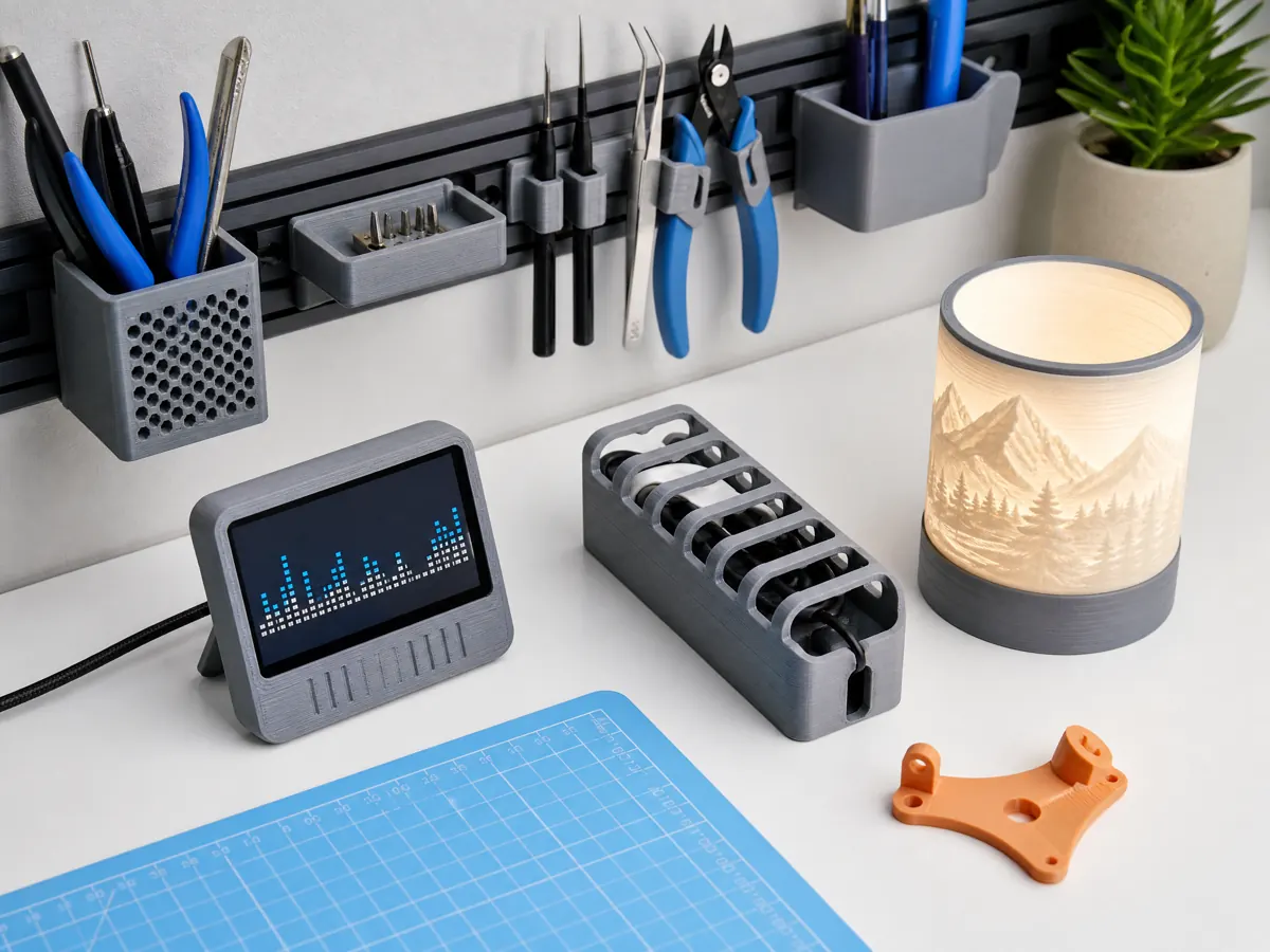
FDM tolerance is the controlled difference between the geometry in CAD and the geometry a printer can make repeatedly. It is not a single number you can copy from another machine. Nozzle diameter, extrusion width, shrinkage, first-layer squish, orientation, material, and cooling all influence the result. A useful tolerance workflow therefore begins with a test part, not a promise.
Separate clearance, interference, and accuracy
Clearance is intentional space between moving or mating parts. An interference fit intentionally makes one feature larger so it presses into another. Accuracy is how close a printed feature is to the modeled dimension. A printer can be accurate in one direction and still need more clearance for a sliding fit because surface texture and layer steps add friction.
For many FDM printers, a starting clearance test might include gaps from 0.10 mm through 0.50 mm in small increments, with larger values for rough surfaces or large parts. That is a test range, not a universal design rule. Print it in the same material, orientation, layer height, and nozzle diameter as the intended part.
Build a fit coupon
Create a small coupon with holes, pins, sliding tongues, snap tabs, and a threaded or captured-nut feature if those matter to your project. Label each feature in the model. After printing, measure with calipers and record which clearances move freely, which require a push, and which fuse.
| Feature type | Test question |
|---|---|
| Sliding rail | What gap moves smoothly without visible wobble? |
| Pin and hole | What diameter difference gives the assembly force you need? |
| Captive nut pocket | Does the pocket account for polygonal corners and first-layer bulge? |
| Lid or enclosure | Does the perimeter allow for material expansion and surface texture? |
Orientation matters
A horizontal hole is made from short bridges and may print undersized or textured at its top. A vertical hole is generally rounder but still affected by line width and flow. A press fit across layer lines behaves differently from a press fit along them. Test the same critical feature in the intended orientation.
Use chamfers and lead-ins to make assemblies more forgiving. A small chamfer can help a screw, pin, lid, or mating part start without scraping the first-layer edge. Design post-processing where it is appropriate: a drilled hole, reamed bore, or heat-set insert pocket can be a more reliable choice than expecting a tiny printed feature to meet a precision requirement directly.
Keep tolerance data with the profile
Record the printer, nozzle, material, build plate, layer height, and date beside each tested clearance. A change from PLA to PETG, a different spool, or a worn nozzle may justify retesting. This small library becomes more valuable than a generic tolerance chart because it reflects the machine and workflow you actually use.
FDM rewards designs that include forgiveness. Test the fit, choose a clearance deliberately, add a lead-in, and leave room for the process. Those habits make assemblies less dependent on a perfect first print and easier to reproduce months later.