ABS and ASA for functional parts: when enclosed printing earns its place
By Let’s 3D Studio · 20 min read
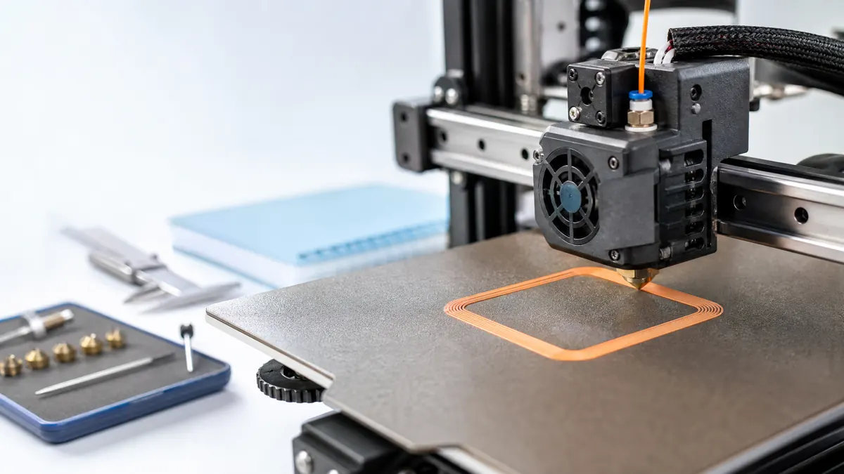
ABS and ASA have reputations: they are rugged, heat-tolerant, and unapologetically picky about their thermal environment. When they print well, they produce strong, functional components that shrug off many of the limitations you might encounter with easier filaments. When they do not, the results can be warping, cracks, and headaches. This guide explains when ABS or ASA is the right choice, how to make enclosed printing pay dividends, and how to troubleshoot with intent rather than guesswork.
We will stay practical: suggested ranges for temperatures and speeds are starting points, not guarantees. Every printer, brand, and geometry is different, so expect small, methodical adjustments.
Why ABS and ASA still matter for functional parts
- Heat resistance and dimensional robustness: ABS and ASA typically maintain stiffness and shape at temperatures that soften many common consumer filaments. For brackets near engines, housings in warm enclosures, or fixtures left in a hot car, they are frequent picks.
- Impact and fatigue performance: They generally tolerate knocks and repeated flexing better than brittle options, useful for snap-fits, clips, and functional hinges with appropriate design.
- Post-processing flexibility: ABS solvent-welds with acetone and similar solvents, making it useful for assembling multi-part structures and smoothing surfaces. ASA bonds with certain solvents as well, though often less aggressively than ABS; mechanical fasteners and adhesives remain common options.
- Outdoor durability: ASA is valued for its far better UV and weather resistance, making it the go-to for outdoor enclosures, signage, and fixtures. ABS can work outside but tends to chalk, fade, and embrittle faster under sun exposure.
ABS and ASA are unforgiving about thermal gradients. If your parts are small, or your ambient air is already warm and draft-free, you may succeed without full enclosure. As part size, thickness, and print time grow, the motivation for an enclosure increases quickly.
ABS vs ASA at a glance
A short, practical comparison to choose the starting material:
| Property | ABS | ASA |
|---|---|---|
| UV/weather resistance | Limited | Significantly better |
| Warping tendency | Moderate to high | Moderate (often slightly friendlier than ABS) |
| Odor during printing | Noticeable styrene smell | Similar, sometimes milder |
| Print temps | High | High (often a bit hotter) |
| Surface finish | Satin to matte | Matte to satin, often crisper details |
| Outdoor use | Not ideal long-term | Designed for it |
If your part lives outdoors or near windows with direct sun, pick ASA first. If you need solvent welding with acetone and plan extensive smoothing, ABS is usually more responsive. For geometry sensitivity and warping behavior, success often depends more on chamber management than on the small differences between the two.
When enclosure printing earns its place
ABS and ASA contract as they cool. Large, flat areas cool at different rates than dense cores and thin edges. Without a stable warm environment, these internal stress differences bend corners up, split layers mid-height, or distort hole sizes.
A decent enclosure reduces drafts and stabilizes air temperature. A heated build plate provides a warm base; the enclosure allows the rest of the part to cool gently rather than abruptly. Consider an enclosure necessary when:
- Parts exceed palm-size dimensions with flat faces.
- Tall or boxy geometries run for many hours.
- You see recurring corner lift in the first third of the build or cracks mid-height.
- Your environment has moving air from HVAC, open windows, or frequent foot traffic.
Not every project needs an active, high-temperature chamber. For many users, a simple, sealed enclosure that keeps air still and modestly warm is enough.
Types of enclosures: quick comparison
| Type | Typical benefit | Caveats |
|---|---|---|
| Simple draft shield or fabric cover | Easiest to add, reduces drafts | Limited temperature rise |
| Rigid DIY acrylic/wood box | Better temperature stability | Watch electronics heat buildup |
| Commercial enclosed printer (passive) | Consistent, clean workflow | Cost; may still need small tweaks |
| Actively heated chamber | Best for large, demanding parts | Complexity, safety, and cost |
Whichever route you choose, avoid trapping your printer’s electronics in a stagnant hotbox. Electronics do better outside the hot chamber or with ducting that isolates them from chamber heat.
Safety and air quality notes
- Fumes and odor: Both ABS and ASA emit fumes with a noticeable styrene-like smell. Use in a well-ventilated space. Air filtration can reduce particulates and odors but does not make enclosed printing safe in poorly ventilated living spaces.
- Heated enclosures: Keep temperatures within your printer’s rated limits. Stepper motors, belts, boards, and PTFE components have temperature ceilings; exceeding them can lead to damage or risk.
- Fire safety: Do not leave printers unattended without appropriate safeguards. Keep flammable materials away from the enclosure, and ensure power and wiring are in good condition.
- Solvents and adhesives: Acetone and similar chemicals are flammable and require good ventilation. Follow manufacturer guidance for handling.
Material prep: how much does drying matter?
ABS and ASA are less moisture-sensitive than nylons, but moisture can still manifest as micro-bubbles, pitted surfaces, inconsistent extrusion, and weak layer bonds. If your filament has been open for weeks in a humid climate, drying can help.
- Drying ranges: 60 to 80°C for 4 to 8 hours is a reasonable starting point. Confirm your spool’s recommended maximum temperature and avoid deforming the spool.
- Storage: Reseal spools with desiccant when not in use. For frequent users, a dry box that feeds filament directly to the printer reduces re-absorption.
You may not see dramatic differences on every roll, but when chasing fine surface quality or tight tolerances on larger builds, consistent dryness helps stabilize extrusion.
Slicer setup: a reliable baseline
These are starting ranges; adjust to your filament brand, hotend, and enclosure behavior.
- Nozzle temperature:
- ABS: 230 to 260°C
- ASA: 240 to 265°C Use the lower end for smaller parts and slower speeds; the higher end for larger parts, higher speeds, or very low cooling. If layers look matte and underfused or you see layer splitting, a small temperature bump can help.
- Bed temperature:
- ABS: 95 to 110°C
- ASA: 95 to 110°C Increase for larger contact areas or if corners lift. Decrease slightly if you get excessive elephant’s foot even with compensation.
- Chamber or enclosure: Aim for a stable, warm environment. Many printers with passive enclosures settle around 35 to 50°C. Larger parts benefit from the higher end of this range if your machine can safely maintain it.
- Part cooling fan: Minimal or off for most of the print. Use brief, targeted cooling for bridges or very fine features, then disable again to avoid creating cold spots that trigger layer cracks.
- First layer strategy:
- First layer height: 0.20 to 0.30 mm
- First layer speed: 15 to 25 mm/s
- First layer bed temperature: keep at the high end of your range
- Enable a brim (6 to 12 mm) for parts with sharp corners or long edges.
- Print speed:
- 30 to 60 mm/s for perimeters
- 40 to 80 mm/s for infill Use the lower end if you see under-extrusion during long, hot runs; the upper end with hotter nozzle settings and proven adhesion.
- Wall and infill:
- Perimeters: 3 to 5 lines for structural parts
- Infill density: 15 to 40 percent, depending on load. Avoid very high density unless necessary; it increases internal stresses and warping.
- Retraction:
- Direct-drive: 0.6 to 1.2 mm at 20 to 35 mm/s
- Bowden: 2.5 to 5.0 mm at 25 to 45 mm/s Keep retractions conservative; excessive retraction at high temps can promote heat creep and jams.
Cooling strategy, exceptions and bridges
Most of the time, run minimal part cooling with ABS/ASA. Bridges and sharp overhangs are the exceptions. Use a small burst of fan, perhaps 10 to 25 percent, only during those features, and let the part rest in the warm air otherwise. If you start to see mid-height cracks shortly after enabling cooling, reduce that cooling and consider a slower bridge speed.
Adhesion strategy: surfaces and helpers
Plate choices:
- PEI sheets: Consistent and convenient. Refresh with isopropyl alcohol when cool, and avoid over-sanding; a light scuff restores grip.
- Smooth glass or mirror: Works with a glue stick layer or specialized sprays. Offers a flat bottom surface and easy release once cool.
- Garolite and textured sheets: Can grip too aggressively when hot; test slowly to avoid part damage during removal.
Adhesion helpers:
- Glue stick or specialized bed adhesives create a release layer and even out micro-variations.
- Prefer manufacturer-approved bed adhesives or glue-stick release layers; avoid preparing improvised solvent mixtures in a home workspace.
- Brims or skirts pre-warm the nozzle path and stabilize the first layer.
Elephant’s foot compensation:
- Slight chamfers on the model’s bottom edges (0.2 to 0.4 mm) or slicer-based first-layer horizontal expansion reduction help maintain dimensional fidelity when the first layer is printed hot.
Designing with ABS and ASA in mind
Thermal shrinkage and stress inform good geometry:
- Fillets and radii: Soften inside corners with fillets to reduce stress concentration and warping at sharp transitions.
- Uniform wall thickness: Keep similar cross-sections along the build to avoid hot cores and cold edges.
- Ribs over mass: Instead of very thick walls, use ribs and gussets to add stiffness with less material, reducing the risk of internal stress-induced warp.
- Bosses and inserts: For screws, design robust bosses with generous radii at their base. For repetitive assembly, heat-set inserts offer durable threads; leave material around the insert to resist push-out and cracking.
- Shrinkage tolerance: Large ABS and ASA parts can finish slightly undersized. As a starting approach, test a small calibration coupon and, if needed, consider a uniform scale adjustment of roughly 0.2 to 0.8 percent for large, boxy components. Adjust per axis if your printer shows directional bias.
- Holes and pins: Holes often print undersized. Add 0.2 to 0.4 mm to the hole diameter in the model, or use horizontal expansion compensation in the slicer. Where precision matters, plan to drill to final size after printing.
Orientation:
- Align the main load path with the layer lines in mind. For bending loads, orient the part so perimeters resist the tension side.
- For snap-fits, design the flexing arm so that layers run parallel to the length of the arm when possible, reducing the risk of inter-layer crack initiation.
Warping and layer splitting: diagnose, don’t guess
Symptoms tell you where thermal management is failing.
- Corners lifting in the first third of the build:
- Root causes: insufficient bed adhesion, cold bed, drafts, or too thin a first layer. Also, large solid infill early in the build can contract and lever edges upward.
- Actions: raise bed temperature within your safe range; expand the brim; apply a better adhesive layer; slow the first layer; reduce early infill density or use gradual infill steps; verify Z offset for a slightly squished first line.
- Mid-height cracks around the perimeter:
- Root causes: cold ambient air hitting a warm part, too much part cooling, low extrusion or nozzle temperature, chamber temp too low for the geometry, or high internal stress from thick cross-sections.
- Actions: shield the part from drafts; reduce or disable the fan except for bridges; increase nozzle temperature slightly; improve enclosure sealing; consider a brief pause to let the chamber equilibrate if long prints strain the thermal balance.
- Edge curling at upper layers near overhangs:
- Root causes: insufficient support or local cooling, leading to droop or uplift that becomes a snag point.
- Actions: add or improve supports with modest interface spacing; use a small fan burst only in that area; slow down outer walls on steep overhangs.
- Large flat lids bowing upward:
- Root causes: internal stress in thick, wide top infill and rapid cooling at the top surface.
- Actions: slow top layers; consider lower top infill line width or pattern that balances stresses; if possible, break the design into smaller panels or add ribs and contour that resist bow.
Record changes one at a time. ABS and ASA respond better to consistent, incremental tuning than to sweeping changes that mask what actually helped.
Surface quality: taming strings, blobs, and seams
- Strings and wisps:
- Dry filament, correct temperature, and gentle retraction reduce strings. Slightly higher travel speeds, 150 to 200 mm/s if your motion system is accurate, give molten polymer less time to stretch.
- If strings persist, lower the nozzle temperature in small steps or shorten retraction distances, particularly on direct-drive extruders at high temps.
- Z-seam artifacts:
- Use aligned seams on a hidden edge or a rear corner if cosmetics matter less there. Coasting and wipe strategies can help, but be cautious: excessive coasting leads to thin outer walls and weak spots.
- Over-extrusion pips at layer starts:
- Reduce pressure buildup by decreasing acceleration or using pressure advance/linear advance features if your firmware supports them. Start with modest values and check perimeters for consistent thickness.
- Matte vs glossy bands:
- Banding often indicates fluctuating chamber temperature or inconsistent filament flow. Ensure the enclosure is stable, and check that filament feeds smoothly with minimal drag through any dry box or guide.
Strength tuning for real loads
- Perimeters carry a surprising amount of load in bending. Use 4 to 5 perimeters for high-stress brackets, keeping infill moderate (20 to 35 percent). This balances strength with shrinkage control.
- Infill patterns like gyroid or grid offer good isotropy for general use. If loads are strongly directional, consider orientations and perimeters that align with the major stress direction.
- Top and bottom layers should be thick enough to distribute load: 6 to 10 solid layers at 0.2 mm each is a common starting range for functional plates or covers.
Fasteners:
- Pilot holes that are too small will cause stress risers and cracks. Size holes conservatively and test on scrap prints. For self-tapping screws, leave enough wall thickness and fillet bases to avoid splitting.
- Heat-set inserts yield repeatable assembly. Warm the insert carefully and press in with a flat tool or jig; allow the plastic to resolidify without movement for best retention.
Outdoor performance and color choice
ASA is formulated for UV stability and generally keeps its appearance and mechanical integrity outdoors longer than ABS. If you must use ABS outside, prefer a design that minimizes sun exposure and consider protective coatings or paint rated for plastics.
Color affects heat absorption: dark colors warm more in sun, which can increase softening and deformation risk. Lighter colors or reflective finishes reduce heat gain. For enclosures near electronics, this is a subtle yet useful factor.
Post-processing: solvent, sanding, and assembly
- Solvent welding:
- ABS responds readily to acetone and similar solvents, allowing strong solvent-welded joints along designed seams. Apply sparingly with a brush or applicator, and clamp until set.
- ASA is generally more resistant. Some blends soften slowly with acetone or other solvents like MEK; test on scrap before committing. Where solvent response is weak, use mechanical fastening or adhesive designed for plastics.
- Smoothing and finishing:
- Acetone vapor smoothing presents serious flammability and inhalation risks; use a professional, manufacturer-directed process rather than improvised home vapor methods. Smoothing trades crisp detail for rounded surfaces.
- ASA often sands to a crisp matte finish. Use progressive grits, moving to primer and paint as needed. Light filler primer helps flatten layer lines without much mass.
- Machining operations like drilling or tapping should use moderate speeds and minimal pressure to avoid heat buildup. Back out often to clear chips.
- Painting and coatings:
- Clean with isopropyl alcohol and use a primer compatible with ABS/ASA. For outdoor parts, choose paints and clear coats specified for UV exposure and temperature swings.
Cost and throughput: when the juice is worth the squeeze
An enclosure adds complexity and sometimes money, but it converts a string of near-misses into predictable success on demanding parts. Consider the cost of failed large ABS plates or housings: wasted time, filament, and opportunities. If your use case includes:
- Repeatedly printing brackets, housings, or fixtures larger than your palm
- Outdoor installations or warm service environments
- Parts that must be solvent-welded or mechanically finished
then enclosed ABS/ASA printing usually pays for itself in reliability and part performance.
Example workflows
Two pragmatic setups you can adapt.
Indoor equipment bracket, ABS, medium size
- Geometry: 150 mm bracket with two ribs and a 6 mm mounting boss
- Material choice: ABS for solvent-welding a cable guide and tapping threads
- Setup:
- Enclosure: passive box with sealed panels; electronics outside or ventilated
- Nozzle: 245°C start, adjust 5°C up if layer bonds feel weak
- Bed: 105°C, PEI sheet cleaned when cool
- Chamber: allow 10 to 15 minutes warm-up after bed hits temp
- Cooling: off, except 20 percent during two short bridge spans
- Speed: 40 mm/s perimeters, 60 mm/s infill
- Perimeters: 4; Infill: 25 percent gyroid
- First layer: 0.25 mm, 18 mm/s, 10 mm brim
- Diagnostics:
- If corners lift: add glue stick over PEI near the edges and increase brim to 12 mm
- If mid-height crack appears: bump nozzle to 250°C and reduce bridge fan time window
- Finish:
- Light sanding; acetone brush to solvent-weld the separate guide; clamp for a few minutes
Outdoor sensor housing, ASA, tall and boxy
- Geometry: 120 x 80 x 50 mm enclosure with vents
- Material choice: ASA for UV resistance
- Setup:
- Enclosure: rigid enclosure, seal gaps; keep electronics outside
- Nozzle: 255°C start; willing to go 260°C for tall walls if needed
- Bed: 100°C on glass with thin glue layer
- Chamber: stable warm air, avoid drafts when opening doors
- Cooling: off for walls; 15 percent for brief, thin vent slats
- Speed: 35 mm/s perimeters, 55 mm/s infill
- Perimeters: 5; Infill: 20 percent grid
- First layer: 0.25 mm, slow; 8 mm brim
- Diagnostics:
- If vents distort: slow perimeters in vent regions and add a small fan burst only during those layers
- If top lid bows: reduce top infill line width and slow top layer speed; consider adding internal ribs in the design
- Finish:
- Wet sand to matte; prime lightly; paint in a light color to reduce sun heating
Maintenance and printer considerations
- Hotend: All-metal hotends handle the higher temperatures associated with ABS/ASA more reliably than PTFE-lined hotends at the nozzle. If you have a PTFE-lined system, stay within its rated maximum temperature and check the liner condition regularly.
- Nozzle: Brass is fine for unfilled ABS/ASA. If you use fiber- or mineral-filled variations, switch to a hardened nozzle to slow wear.
- Bed flatness: Check that your bed is level and flat. Mesh compensation helps, but severe peaks or dips will complicate first-layer adhesion for warp-prone materials.
- Extruder path: Ensure smooth filament feeding with minimal friction in any guides or dry boxes. Sticky paths become more troublesome at higher temperatures and lower cooling.
Troubleshooting quick reference
| Symptom | Likely cause | First fixes |
|---|---|---|
| Corners lifting early | Bed too cool; poor adhesion; drafts | Increase bed temp; add brim; use glue or ABS slurry; improve enclosure sealing |
| Mid-height perimeter cracks | Chamber too cool; fan on; low nozzle temp | Disable fan except for bridges; raise nozzle temp slightly; pre-warm chamber |
| Stringing between features | Nozzle too hot; excessive retraction; moist filament | Lower temp; shorten retraction; dry filament; increase travel speed |
| Surface zits at seam | Pressure buildup; aggressive coasting/wipe | Reduce coasting; enable pressure advance cautiously; lower acceleration |
| Top layer ripples or sink | Printing too fast/hot; internal stress | Slow top layers; balance infill pattern; ensure steady chamber temperature |
| Poor bridge quality | Insufficient cooling or speed control | Enable brief, low fan only on bridges; reduce bridge speed; tune line width |
| Jamming on long prints | Heat creep; excessive retraction; fan off on hotend heatsink | Reduce retractions; ensure heatsink fan runs; slightly lower nozzle temp |
Use the table as a starting map; each printer and filament responds differently, so verify results with small test pieces before committing to long builds.
Pushing dimensionally accurate results
For assemblies and tight fits:
- Calibrate flow: Over-extrusion skews dimensions. Print thin-wall and single-extrusion calibration models to dial in extrusion multiplier.
- Horizontal expansion: Many slicers offer first-layer and overall XY compensation. Adjust a few tenths of a millimeter for press-fit interfaces.
- Shrinkage over long spans: Tall or wide parts may scale unevenly. Measure test coupons and compensate per axis. If you see repeatable undersize in X more than Y, check belt tension and gantry geometry alongside scaling tweaks.
When to choose PETG or Nylon instead
The right material depends on environment and mechanics:
- PETG: Friendlier to print than ABS/ASA, good layer adhesion, and chemical resistance. Its glassy behavior can be less tolerant of high heat and wear in hot, sun-exposed situations. If odor, enclosure complexity, and modest heat needs define your project, PETG may be the pragmatic choice.
- Nylon and blends: Excellent toughness and fatigue resistance, but far more moisture-sensitive. Drying is essential, and enclosures still help. If you need living hinges or severe impact tolerance, nylon may outperform ABS/ASA at the cost of trickier handling.
Consider prototype iterations in PETG for fit, then move to ABS/ASA for final parts that need heat and outdoor durability.
Practical notes on large-format ABS and ASA
As parts cross the 200 mm mark in any dimension, small details in setup matter more:
- Let the chamber equalize: Preheat the bed and allow the enclosure to warm the air for 10 to 20 minutes before starting.
- Ramp infill gradually: Some slicers support infill step-ups that avoid sudden mass changes in the part, reducing stress spikes.
- Split the part: Add tongue-and-groove joints or lap seams and solvent-weld later. Multiple smaller prints can outperform a single massive print if warping risk is high.
- Add mouse ears: Small discs at sharp corners increase contact area locally without a full brim; they are easy to trim post-print.
Quality control and repeatability
- Document working profiles: Once you find a stable combination of temps, speeds, and adhesion aids for a filament brand and color, save it as a named profile. ABS and ASA formulations vary by brand and even by color.
- Control your room: If the printer room varies widely day to day, expect more drift in results. Passive environmental consistency helps as much as slicer tinkering.
- Inspect first layers: The first layer tells you much about the rest of the print. Smooth, slightly compressed lines with uniform sheen imply correct Z offset, temperature, and cleanliness.
A note on energy, noise, and workflow
Enclosures reduce fan noise and keep the printer’s acoustic footprint contained. However, higher bed temperatures and warm chambers draw more power. If noise and energy are considerations, cluster ABS/ASA jobs to make the most of a single warm-up cycle and preheating period. Plan material changes and maintenance for the cool-down windows.
Common myths, clarified
- Bigger nozzles always reduce warping: Larger nozzles deposit more heat and mass, which can help layer bonding but can also introduce more internal stress if cooling is uneven. Use them thoughtfully; do not expect them to be a silver bullet.
- More infill equals stronger parts: Past a certain point, added infill increases stress and warp risk more than it adds usable load capacity. Optimize perimeters, orientation, and ribbing first.
- Fans must be fully off: While usually minimal, targeted, low-speed cooling for bridges or small details can improve results without causing layer cracks, provided your chamber remains warm and draft-free.
Bringing it together: a concise playbook
- Choose material:
- ASA for outdoor or UV exposure; ABS when you need solvent-welding responsiveness or interior components with consistent heat resistance.
- Stabilize the environment:
- Enclosure first; then tune bed, nozzle, and chamber temperatures. Keep electronics cool.
- Secure the first layer:
- Clean surface, appropriate adhesive, brim or mouse ears, deliberate first-layer speed and height.
- Minimize thermal shocks:
- Little to no part cooling except for bridges, and only briefly.
- Design for the material:
- Ribs over bulk, fillets on corners, generous bosses, thought-out orientation, and allowance for shrinkage.
- Iterate with intent:
- Change one variable at a time. Use small test coupons to confirm direction before launching a 10-hour build.
Conclusion
ABS and ASA reward printers configured to manage heat thoughtfully. If you are printing small parts on an open machine, you might scrape by with careful bed prep and conservative settings. As parts scale up and requirements tighten, an enclosure earns its place by turning borderline letters of the alphabet into reliable, repeatable builds.
Start with sane, conservative ranges for temperature, speed, and cooling. Keep the air still and warm. Give corners a fighting chance with brims, fillets, and adhesives. For outdoor parts, let ASA do what it was made for; for interior assemblies and solvent-welded structures, play to ABS’s strengths. As with any material, measure your results, record what works, and refine. With a stable chamber and methodical tuning, ABS and ASA become dependable tools for functional parts that last where easier filaments bow out.